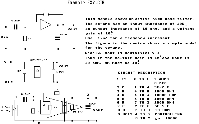
Labels:text | diagram | font | line | number | black and white | plan | technical drawing OCR: Example EX2. CIR 1K 0.SUF This sample shows an active high pass filter. The op-amp has an input impedance of 10K , Vout an output impedance of 10 ohm, and a voltage Uin 50 UF gain of 10. 1K Use -1.33 for a freqency increment. The figure in the centre shows a simple model for the op-amp. Cearly, Vout is Rout#gm (V+-U-) 9M(V+-V-) Thus if the voltage gain is 10 and Rout is U- 10 ohm, gm must be 10. Vout Rin Rout CIRCUIT DESCRIPTION 0 TO 1 1 AMPS V+ . 1 IS 0 DEG 2 C 1 TO 4 5E-7 F 1K 3 R 4 TO 0 1000 OHM @.SUF 1 2 4 R 4 TO 3 10000 OHM 4 5 R 3 TO 1000 OHM 3 SOUF 6 R 3 TO 2 1000 OHM Amp 7 C 2 TO 5E-5 F @ Dcg 1K 10 ohm Vout 8 2 TO 10 OHM 9 VCIS 4 TO 3 CONTROLLING TO 2 gm= 10000